Tel: 54 11 4251 3134
Cel: 15 4418 8384
Fax: 54 11 4251 3134
9 de julio 384
CP 1876 Bernal- Pcia. Bs. As
rminstrumental@rminstrumental.com


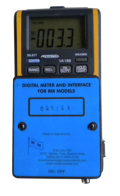
El Medidor Digital e Interface para Modelos RM Modelo MD & I es un dispositivo intermedio entre un sensor RM y la computadora. El sensor mide la variable específica, transmite este valor al MD & I y éste lo muestra en un display y además transmite este mismo valor a la computadora. La importancia de este Kit de dispositivos es que adquiriendo solamente una unidad de MD & I, se pueden medir todos los parámetros que ofrece la línea de sensores RM, solamente cambiando el tipo de sensor, pues el conjunto está construido de tal modo que las respuestas de todos los sensores es similar y va del valor cero a escala total y en forma lineal. Se puede optar por el uso de este dispositivo solo sin la computadora, pues las lecturas se ven en el display, disponiéndose de los valores máximo, mínimo, hold, o de tiempo real a 3 lecturas/segundo.
Sensores RM: Los sensores RM son transductores que transforman la variable a medir en una señal eléctrica compatible con el MD & I.
Las variables que se pueden medir son:
Productos químicos de gases y vapores tales como: NH3, CO, AsH3, PH3, GeH3, HCN, Cl2, HCl, SO2, NO2, NO, O2, O3, SH2, CFCs, H2, CO2, dióxido de cloro, etileno, óxido de etileno, hidrocarburos, sulfuros volátiles, aminas, cetonas, alcoholes, éteres, aldehídos, mercaptanos, smog, fume, mist y sistemas similares (humo de cigarrillo, gases de caños de escape de motores nafteros y gasoleros, humos de soldaduras), etc. Están incluidos los Alcoholímetros y Acetonímetros.
Material Particulado de Rango Higiénico (PM10) provenientes de diversas industrias de procesos pulverulentos.
Temperatura, Humedad, p.p.m. de agua, Presión absoluta o diferencial, T.G.B.H. o Carga Térmica.
Vibraciones, Radiaciones (ionizantes, IR, Visible, UV), Puesta a Tierra, Campos Magnéticos, Velocidad del Aire, etc.
Estos sensores pueden estar instalados en el mismo gabinete del MD & I, o en otro gabinete unido por varios metros de cable con conectores standard.
La característica más importante, es que las respuestas de todos los sensores RM son universales al MD & I de modo que si disponemos de sensores instalados en gabinetes independientes, podemos efectuar mediciones de distintos contaminantes físicos y/o químicos por simple desconexión de uno y conexión de otro.
El MD & I es compatible con toda la línea de sensores RM.
El encendido de los sensores se efectúa con una llave a corredera ubicada en el gabinete del MD & I. Un LED verde encendido indica cuando el sensor está activo.
El Medidor Digital e Interface para Modelos RM Modelo MD & I presenta los siguientes controles:
Llave a corredera: Enciende y apaga el MD & I y el sensor correspondiente.
LED verde: Indica que el sensor correspondiente está midiendo.
SELECT: Esta tecla es para funciones especiales y no debe ser pulsada.
RANGE: Esta tecla es para funciones especiales y no debe ser pulsada. Cuando se enciende el equipo el display indicará ún número de lectura de tres números enteros y un decimal, por ejemplo 123.4 y a la derecha del mismo indicará el rango en que debe trabajar, que deberá ser siempre en mV. Las otras escalas indicarán en V y no deben ser utilizadas. Se reserva su uso para otras operaciones. A la izquierda aparecerá la leyenda DC y dos líneas horizontales, una llena y la otra punteada, indicando que la lectura es correcta.
REL: Esta tecla da el modo de medidas relativas con respecto a una medida que tomamos como patrón. Si la pulsamos aparecerá en el display la leyenda REL. Se utiliza en mediciones especiales.
Hz/DUTY: Con el equipo apagado pulsar esta tecla y dejar pulsada. Encender el equipo y luego liberar la tecla. Se encenderá en el display la leyenda PC-LINK indicando que está activa la salida a la PC.
HOLD/LIGHT: Con pulsación corta activa el modo de “congelar” la lectura en el display, o sea deja como lectura permanente la lectura de tiempo real al momento de pulsar. Aparecerá en este caso una H en el display. Con pulsación de 2 segundos enciende la luz interior o backlight.
MAX/MIN: Durante el tiempo de una medición si pulsamos brevemente este botón dará el máximo de la medición y se encenderá en el display la leyenda MAX. Pulsando brevemente otra vez este botón indicará de la misma manera el mínimo, situación que será indicada por la leyenda MIN. Pulsando este botón por 2 segundos retornará a las mediciones en tiempo real, dando 3 lecturas/segundo.
Propiedades:
Medidor: Display de cristal Líquido de 3 5/6 dígitos.
Lecturas en el Display: 3/segundo.
Sobrerango en el Display: Indicará “OL”.
Temperatura de Medición: 0 a 40 ºC de la interface. El sensor específico puede reducir este intervalo.
Condiciones de Almacenamiento: -10 a 60 ºC e inferior al 70% de humedad relativa ambiente. El sensor específico puede reducir este intervalo.
Alimentación: Una batería de 9V de buena calidad tipo 6F22. Cuando la batería instalada está agotada, se encenderá el icono de la batería en el display. En este caso se debe reemplazar del compartimiento posterior.
Dimensiones sin el gabinete superior: 180 mm. x 85 mm. x 40 mm.
Peso con baterías sin el gabinete superior: 310 gramos aproximadamente.
Accesorios Incluidos: Una batería de 9V, cable USB para computadora; CD para instalar en la computadora el USB driver y el software; Gabinete de transporte, Instrucciones de Uso y Certificado de Calibración.
SOFTWARE Y COMPUTADORA
El software del MD & I y el USB driver contenido en el CD debe ser instalado en la computadora.
Los requerimientos del sistema operativo que debe cumplir la computadora son:
Windows 98se/ Windows ME/Windows XP/ Windows 2000/Windows Vista 32bit o 64 bit/Windows 7 32 bit o 64 bit.
Conectar el cable USB entre la Interface y la computadora. Abrir el programa PC Link. Cliquear set. Cliquear system set, Cliquear COM (el que corresponda al puerto serie seleccionado en la PC), Cliquear Apply, Cliquear Start. Aparecerán los valores de la medición en pantalla. Terminada la medición cliquear stop. Cliquear File. Cliquear Save, Export graph o Export Excel. Cliquear Exit. Establecer en todos los casos el sampling rate (lecturas/minuto) y guardar los datos de la medición en una carpeta creada a tal fin. Se sugiere establecer por cada medición un número de protocolo consecutivo y creciente. Se sugiere también confeccionar y tener para siempre una misma plantilla de protocolo para no olvidar ingresar datos de la medición. En la planilla o plantilla de protocolo tipo tendrían que figurar datos como: Fecha, lugar, horario de medición, parámetro a medir, unidades, instrumental utilizado, condiciones de operación o proceso, condiciones atmosféricas, descripción del proceso, gráficos, etc. para una medición industrial, u otros datos para una medición por ejemplo de alcoholemia.
Cuando se obtenga la lista de los valores numéricos, se verán que estas columnas de valores van acompañadas de otras columnas de signos. Tomar solamente la columna de valores numéricos con el signo matemático que corresponde solamente al valor indicado. Para esta aplicación los signos no son necesarios, pero sí los que indican y cuando corresponda, al valor numérico, que sería por ejemplo el caso de la medición de vibraciónes o de temperaturas. Se pueden llevar todos los valores a otro programa, donde tengamos el protocolo tipo. Puede ser por ejemplo el Excel u otro. Con la serie de valores obtenidos se podrán efectuar gráficos, promedios, etc.
No someter al equipo a golpes, maltratos o ambientes corrosivos.
Las características técnicas pueden ser cambiadas sin previo aviso.
ContactoDigital Meter and Interface for RM Models Model MD & I is an intermediate device between RM and the computer sensor. The sensor measures the specific variable, transmits this value to the MD & I and this is shown on a display and also transmits the same value to the computer. The importance of this kit is that acquiring device only an MD & I can measure all parameters that gives the sensor line RM, only changing the type of sensor, since the assembly is constructed such that responses of all sensors is similar and the value is zero and full scale linearly. You can choose to use this device without the computer, because the readings are on display, provided the maximum, minimum, hold, or real-time 3 readings / second..
RM Sensors: Are transducers that convert the variable to be measured into an electrical signal compatible with the MD & I.
The variables that can be measured are:
Chemicals gases and vapors such as NH3, CO, AsH3, PH3, GeH3, HCN, Cl2, HCl, SO2, NO2, NO, O2, O3, H2S, CFCs, H2, CO2, chlorine dioxide, ethylene oxide ethylene, hydrocarbons, volatile sulfides, amines, ketones, alcohols, ethers, aldehydes, mercaptans, smog, smoke, mist and similar systems (cigarette smoke, gas exhaust pipes and gasoline engines, welding fumes), etc. Included are Breathalyzers.
Hygienic Range Particulate Matter (PM10) from various process industries powdery.
Temperature, Humidity, p.p.m. water, absolute or differential pressure, WBGT or thermal load.
Vibration, radiation (ionizing, IR, Visible, UV), Grounding, Magnetic Fields, air velocity, etc..
These sensors can be installed in the same cabinet MD & I, or another cabinet joined by several meters of cable with standard connectors.
The most important feature is that the responses of all sensors are universal to MD & I so if there are sensors installed in separate cabinets, we can make measurements of different contaminant physical and / or chemical one single disconnection and connection another.
The MD & I is compatible with the entire line of sensors RM.
The ON of the sensors is done with a key to the cabinet slide located in the MD & I. A green LED indicates when the sensor is active.
The Digital Meter and Interface for Models RM Model MD & I has the following controls:
Key to slide: Turns ON/OFF the MD & I and the corresponding sensor.
Green LED: Indicates that the corresponding sensor is measuring.
SELECT: This button is for special functions and should not be pressed.
RANGE: This key is for special functions and should not be pressed. When the computer is turned the display will show a number of reading of three numbers and a decimal, eg 123.4 and its right indicate the range in which to work, it must always be in mV. The other scales indicated in V and should not be used. Reserves its use for other operations. On the LCD appears the legend DC and two horizontal lines, one full and one dotted, indicating that the reading is correct.
REL: This mode gives key measures with respect to a measure that we take as a standard. If the press will be displayed REL legend. Special measurements used.
Hz / DUTY: With the power off press this button and let down. Turn on the computer and then release the button. Lights on the display PC-LINK legend indicating that output is enabled the PC.
HOLD / LIGHT: With short press activates the mode to «freeze» the reading on the display, or be left as permanent reading real time reading when pressed. Appears in this case an H on the display. With 2 seconds pressing interior light or backlight.
MAX / MIN: During the time of a measurement if you press this button briefly give the maximum of the measurement and the display will light the legend MAX. Pressing this button again briefly indicate the same way the minimum, that position is indicated by the legend MIN. Pressing this button for 2 seconds will return to real-time measurements, giving three readings / second.
Properties:
Meter: Liquid Crystal Display 3 5/6 digits.
Readings in Display: 3/segundo.
Overrange on Display: indicate «OL».
Measuring temperature: 0 to 40 º C interface. The specific sensor can reduce this range.
Storage conditions: -10 to 60 ° C and below 70% relative humidity. The specific sensor can reduce this range.
Power: One 9V battery 6F22 good quality. When the installed battery is exhausted, the On battery icon on the display. In this case you should replace the rear compartment.
Dimensions without upper cabinet: 180 mm. x 85 mm. x 40 mm.
Weight with batteries without the upper cabinet: 310 grams.
Accessories: One 9V battery, USB cable for computer, CD to install on your computer the USB driver and software; Transportation Cabinet, Instructions for Use and Calibration Certificate.
SOFTWARE AND COMPUTER
The MD & I software and USB driver on the CD must be installed on the computer.
The operating system requirements to be met by the computer are:
Windows 98SE / Windows ME / Windows XP / Windows 2000/Windows Vista 32bit or 64 bit / Windows 7 32 bit or 64 bit.
Connect the USB cable between the interface and the computer. Open the PC Link. Clicking System set, clicking COM (corresponding to the selected serial port on the PC), clicking Apply, clicking Start. Values appear on-screen measuring. After the measurement stop clicking. Clicking File. Clicking Save, Export or Export Excel graph. Clicking Exit. Set in all cases the sampling rate (readings / minute) and store the measurement data in a folder created for this purpose. It is suggested that for each measurement protocol number running and growing. It is also suggested to make and have always the same protocol template to not forget to enter the measurement data. The template protocol type should include information such as: date, place, time measurement, parameter measured, units, equipment used, or process operating conditions, weather conditions, process description, graphics, etc. for industrial measurement, or other measurement data for a breath sample.
When you get the list of numeric values, you will see that these columns of values are accompanied by other signs columns. Take only the numeric column with the mathematical sign that belongs only to the specified value. For this application, the signs are not necessary, but those that indicate and when applicable, the numerical value, which would for example for measuring vibration or temperature. You can take all values to another program, where we have the protocol type. It may be for example Excel or other. With the range of values obtained may be made charts, averages, etc.. etc. Do not subject the team to beatings, abuse or corrosive environments.
Technical characteristics may be changed without notice.
Contact Us